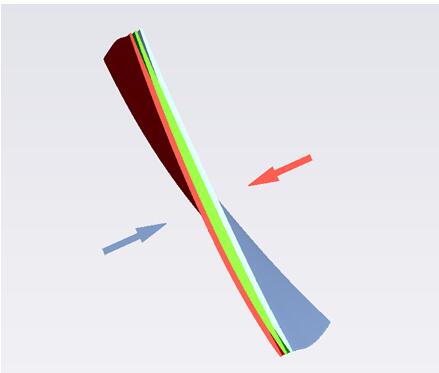
[blade actual photo] - Again, such extremely thin blades tend to cause slight blade bending under the force of the measurement when measuring the top section (as shown in the figure below, when the blade is measured, the blade is subjected to the force of the force to bend toward the back of the blade, and vice versa). Although the amount of bending deformation is not large, considering the extremely thin blade itself, the relative deformation amount is still very considerable, which has a very large influence on the contour and position of the measured blade type. In particular, when measuring the leading and trailing edges of the blade, the actual blade profile is inevitably subject to the shape and/or positional deviation of the theoretical model, so that the incident light direction set according to the theoretical model cannot be orthogonal to the actual profile. If the angle range of the incident light allowed by the probe is larger, the fault tolerance of the probe is better. Otherwise, the angle of the incident light is slightly deviated, and the probe cannot receive the reflected light signal, resulting in the missing point. The CORE White Light Blade Measurement System is an optical, non-contact point-scan measurement device designed and optimized for blade measurement in both hardware and software. CORE-DS's white spot probe uses white light as the light source. It has higher resolution than contact measurement and its spot diameter is only 35μm. It can detect the smallest geometric features and defects on the surface of the measured object, especially Suitable for the measurement of the inlet and outlet sides of the blade. CORE uses a white light probe for measurement, which can avoid the stylus radius compensation error that the contact probe is prone to during the measurement of the blade, which makes the measurement result more accurate. Compared to other optical measuring equipment, CORE-DS's white light measuring head has high applicability to the surface of the object. It can be measured without any treatment on the surface of the object. The objects that can be measured include high-gloss surfaces, black surfaces and even mirrors. Object, and the angle between the light and the surface of the object can be as low as 5°. From the measurement results, the maximum thickness of the blade is 0.7 mm, the maximum chord length is 11 mm, and the exhaust rim radius is only 0.075 mm. Test results show that CORE has the ability to measure very small blades and is more effective than contact probes and other optical probes.
Elevator ropes are highly engineered and made of steel with other composites. Also they are not single wires but several strands of various sizes wrapped together. A typical cable or rope can have over 150 strands of wire precisely designed to be strong, flexible, and give long service. Multiple wire strands are used to increase the life of the cable and give flexibility. When you run a cable over a pulley wheel or sheave, the part of the wire on the sheave makes a shorter trip than the outside of the wire. This stretching over time would create weakness for a single strand. So elevator ropes are flexible strong and give long life if maintained properly.
The types of rope in an elevator can vary depending on the job that they need to do. Here are some of the more common ropes you can find lurking in your hoistway:
Elevator Cable,Elevator wire rope,Lift ropes,governor rope,Elevator steel wire rope,Elevator steel cable Suzhou Keffran Parts Co.,ltd , https://www.keffran-elevatorsmart.com


1. Hoisting Ropes – These are the ropes you see in all the movies. Several are used to suspend the elevator cab and make the car go up and down. These are also the cables used for the counterweights as the counterweights and elevator car are in the same system. The counterweights do just what they are called; they counter the weight of the elevator car when loaded so it takes less effort to move the car up and down. High-strength ropes are used in high rises due to the required speeds that you see today. For instance the fastest moving elevator car in the world, hits a speed that you would find on freeways; an astounding 45 miles per hour! Ultimately the grade of steel is not only determined by the speed but on the car capacity as well. The heavier the weight the car can lift, the higher strength required.
2. Governor Ropes – A governor is part of elevator safety that you will find in the hoistway or overhead space. The second that an elevator car starts falling or even rising too fast, the governor triggers the safety mounted on the car frame and brings the car to a halt. The governor rope runs over the governor sheave and down to the elevator car and is attached to the safety trip mechanism. The governor rope continues all the way down to the pit and runs under a sheave down there and then makes the journey back to the governor. This governor rope arrangement forms a continuous loop while the elevator moves up and down the hoistway. If the car starts going too fast, centrifugal force pushes flyweights outward in the governor against the spring. In simplistic terms it tells the brakes to kick in and stops the car from falling or rising too quickly. As this entire safety system relies on the governor rope, it is very important that it is reliable and in great working condition.
3. Compensating Ropes – Turns out that all of the cable or rope to make an elevator car go up and down is really heavy. This is especially true for really tall buildings. Think about this; a standard one inch elevator cable can weigh 1.85 pounds per foot. As elevator cable makes several trips up and down the hoistway, this weight can really add up. So compensating ropes [compensate" for all the weight of the hoisting ropes on the car or counterweight side. Probably any elevator that exceeds 100′ of travel needs these ropes that are connected to the sling that holds the car and the counterweight frame.
The most important thing about any elevator rope is that they must be in good operating condition at all times. This means inspected often. The technician when performing routine checks doesn`t just look up the hoistway, nod their head and move on; they must check the ropes closely for proper tension, any wear patterns, the diameter of the rope, any rusting, pitting or breaks in strands, the sheaves, proper lubrication and connections.


Aeroengines are the most critical in aircraft manufacturing and one of the most complex and difficult components, while turbine blades are the largest number of components in aerospace engines. Taking a typical turbofan engine as an example, the whole engine consists of a first-stage fan section, a 13-14-stage compressor section, and a 8-9-stage turbine section. The total number of blades can reach several thousand pieces; the blade height is from 1000 mm to the fan blade. The final stage high pressure compressor blades are less than 20mm, which is extremely different.
For machining and inspection, the extreme and minimum of two extreme size blades are undoubtedly a greater challenge, and they impose more stringent requirements on processing and inspection equipment and methods. This case tests the detection of a typical very small blade in an aero engine, and verifies the feasibility and effect of an optical measuring device for the detection of very small blade type, and theoretically does with several other detection schemes. Contrast.
Measuring difficulties
As can be seen from the above figure, the overall height of the blade is about 13 mm, the width of the blade is about 11 mm, and the maximum thickness at the center of the blade is about 1 mm. It belongs to the smallest type of aero-engine blades, especially the edge portion of the blade is only about 0.2 mm thick. There are many difficulties in measuring:
- First of all, because the blade size is too small, it poses a great difficulty for the clamping. If the clamping part is too small, the clamping may be unstable, but the clamping part is too large and may interfere with the measurement.
- Secondly, if contact measurement is used, the choice of stylus is also a big problem. For such extremely thin blades, if a large measuring ball is used, the front and rear edges of the measuring blade will be stuck, and interference is likely to occur; if a small measuring ball is used, it is easy to cause a wrong direction of the radius compensation and cause the line to be disordered.
- If the blade is scanned with an optical probe, a very high resolution must be required. At the front and rear edges where the blade curvature changes drastically, a point with a sufficiently high density is required to cover the shape of the front and rear edges of the blade. Analyze leaf type related parameters.
First of all, the optical probe is generally required for the surface state of the object, and the surface that is too bright or too dark will have a negative impact on the reflection. Second, due to the particularity of the blade geometry, there is a certain requirement for the working distance of the optical probe. Although some types of optical probes can achieve high measurement accuracy, their working distance is very close, and it is easy to collide with the blade. If the lens is used to obtain a large working distance, the measurement accuracy will be significantly reduced. . The third thing that needs attention is the range of the incident angle of the surface. If the point is taken in the normal direction during the measurement of the part, it will inevitably hit the blind spot. In this case, the vector direction of the incident light needs to be changed. If the incident angle of the optical probe allows a small range of angles, it will cause inconvenience to the measurement.