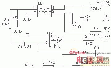
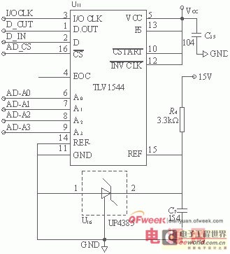
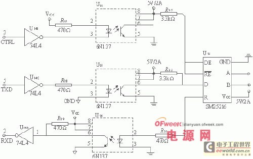
The UPS intelligent monitoring system designed in this paper has the following links and functions: it can operate in various complicated grid environments; it will not generate additional interference to the mains during operation; the output electrical performance indicators should be comprehensive and high. The quality can meet the requirements of the load; the UPS itself should have high efficiency and close to the output power of the actual mains; it is a highly intelligent device with a highly intelligent self-checking function, automatic Display, alarm, status memory and communication functions. introduction UPS power supply system is an essential power source for power, communication, banking and other industries. It has been developing for decades, and its protection function is constantly changing in the process of continuous development and improvement of technology. The UPS can be divided into: backup, online and online interactive according to the working state of the inverter in the host. Their role is to filter and regulate the mains to provide a more stable voltage to the load. At the same time, the electric energy is converted into chemical energy by the charger and stored in the battery. Once the power is interrupted, the grid voltage or the grid frequency exceeds The input range of the UPS can turn on its own reserve power supply in a very short time to supply power to the load. 1, the overall design The design consists of a main monitoring unit, an AC detection unit, a battery detection and inspection unit, a feeder detection and voltage regulation unit, an insulation monitoring and a ground selection unit. These modules communicate with each other through internal RS485 to realize AC power distribution and battery charging of the power cabinet. Real-time monitoring, control and alarm handling of discharge process, battery status, voltage regulation status, bus-to-ground resistance, and feeder line switch status. The entire system communicates with the host computer through RS232 for historical data query and statistics. 2, each unit introduction 2.1 main monitoring unit The main monitoring unit schedules the operation of the entire system. The main monitoring unit consists of the main monitoring board, 320X240 dot matrix liquid crystal display, keyboard and indicator light, etc., to complete the battery charge and discharge management, operation and control parameter setting and display, alarm record storage, query, through RS232 and host computer Communication, control of internal units through RS485. 2.2 AC detection unit The unit mainly completes the acquisition of three-phase AC voltage, current and frequency; at the same time, it has the alarm functions of AC power loss, phase loss, over voltage and under voltage; when the alarm is on, the relay alarm contact is closed. The three-phase AC voltage display value can be corrected by adjusting the potentiometer on the board. 2.3 battery detection and inspection unit The unit consists of a battery detection board and a battery inspection board (optional), which mainly completes the collection of the battery voltage (the mother voltage), the charge and discharge current, the ambient temperature and the cell voltage; the battery fuse state detection; Output analog voltage and current reference to control the voltage or current of other manufacturers' modules or phase-controlled power supply three-phase trigger board (consider with the manufacturer), improve system compatibility; measure on time; Functions such as undervoltage, battery overcharge, battery feed, and single battery failure alarm; the measured values ​​of the combined voltage and the single cell voltage can be separately adjusted by adjusting the potentiometer on the battery test board and the battery patrol board. As shown in Figure 2. 2.4 feeder detection and silicon chain voltage regulator unit The feeder line detects the CPU board and the switch input board, and detects the state of the feeder switch of the mother and the master in real time. Through the switch expansion port, 24 feeders can be detected. When the switch is changed or the voltage of the control voltage is exceeded, the alarm is automatically adjusted and the voltage is controlled by the silicon chain (up to 7 silicon chain voltage regulation). The control voltage display value can be adjusted by adjusting the potentiometer on the feeder detection board. 2.5 insulation monitoring and grounding line selection unit It consists of insulation monitoring board and grounding line expansion board. The main function is to monitor the bus-to-ground resistance and self-positioning grounding branch in real time. When the busbar ground resistance is lower than the alarm set value, the alarm relay is closed; the ground selection line is connected through the ground selection expansion port, and up to 24 line selection lines are supported. 3, the key circuit unit design 3.1 current detection circuit The size of the battery charge and discharge current is especially critical. The circuit diagram is shown in Figure 1. Because it detects both the charging current and the discharge current, the voltage on the small resistor is in two directions. In the circuit detection, two channels are separately detected, which is also convenient for signal conditioning. It is also convenient to measure with one input channel of the AD converter. Figure 1 current detection circuit 3.2 Monitoring of the mother voltage The mother voltage monitoring circuit is shown in Figure 2. The combined voltage flows through the resistors R16, R17, and R54, and is sampled on the resistor R17. Therefore, the resistor R17 should be a high-precision resistor. Since R16 and R54 are much larger than the resistor R17 and appear on the denominator, it is not necessary to use a high-precision resistor. The role of LL is to suppress common mode interference. The magnitude of the voltage to be monitored can be adjusted to meet the input voltage requirements of the AD converter by adjusting the size of the potentiometer Rp. Figure 2 Monitoring circuit of the mother voltage 3.3AD conversion The AD conversion chip uses the TLV1544. The main features of TLV1544 are: wide range of single power supply, VCC can be 2 aids 7 Yao 5 aids 5V; the chip has a high conversion rate inside, the conversion time is less than 10 s s; the chip provides 4 external input channels, through programming For the different status words of the chip, one of the four input channels can be arbitrarily selected; the chip has four ports as the synchronous serial interface, and is connected with the microprocessor through the form of SPI bus; 11-bit AD conversion is enough to meet the requirements of the system. As shown in Figure 3. Figure 3 AD chip circuit Control begins with the sampling of the analog signal input from the selected channel. The sampling of the analog input signal starts from high to low; from low to high, the sample and hold function is held, and analog-to-digital conversion begins. Independent of the input and output clock signals, when it is high, it starts to work. The duration of the sampling period of the switched capacitor array is controlled for low duration. When not in use, connect high. The pin (EOC) goes high at the end of the A辕D conversion to indicate that the conversion is complete. This unit judges whether the conversion is completed or not by reading the EOC level. 3.4 Communication circuit design The entire system communicates via RS485. The specific circuit is shown in Figure 4. Because the control chip uses AT89C52, as the main monitoring unit CPU has only one serial port, and its parallel port is not fully utilized, so the serial port is extended by the programmable serial interface chip 8250, and the parallel port is used to simulate the serial port. 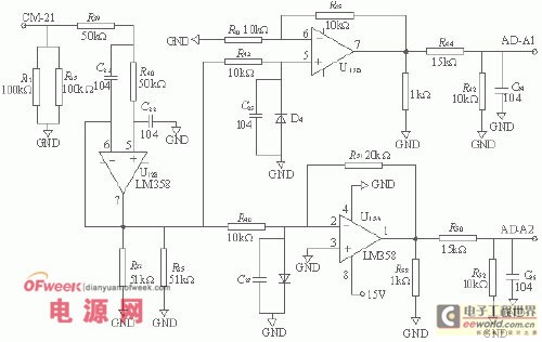
0 times
Window._bd_share_config = { "common": { "bdSnsKey": {}, "bdText": "", "bdMini": "2", "bdMiniList": false, "bdPic": "", "bdStyle": " 0", "bdSize": "24" }, "share": {}, "image": { "viewList": ["qzone", "tsina", "tqq", "renren", "weixin"], "viewText": "Share to:", "viewSize": "16" }, "selectShare": { "bdContainerClass": null, "bdSelectMiniList": ["qzone", "tsina", "tqq", "renren" , "weixin"] } }; with (document) 0[(getElementsByTagName('head')[0] || body).appendChild(createElement('script')).src = 'http://bdimg.share. Baidu.com/static/api/js/share.js?v=89860593.js?cdnversion=' + ~(-new Date() / 36e5)];