Qb Led Grow Light,Quantum Board Grow Light,Grow Light Quantum Board,Quantum Board Led Shenzhen Pvison Technology Co., Ltd. , https://www.pvisunggrowlight.com DCT structure features
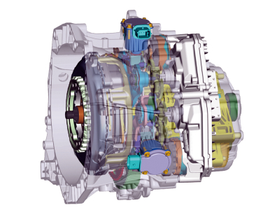
Figure 1 DCT external structure 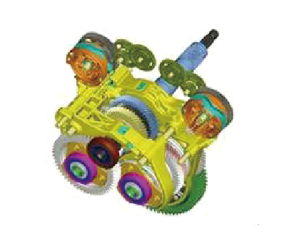
Figure 2 DCT local structure 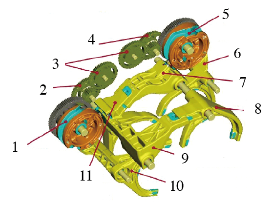
Figure 3 internal input shaft assembly
1, 5. moving drums 2, 3, 4. double flywheel 6. reverse gear, four gear shift fork 7. two, six gear commissure 8, 9. three gear commissure 10. one, five gear shift fork 11. Second and sixth gear moving fork 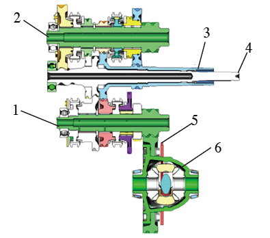
Figure 4 DCT internal projection and physical perspective
1. Output shaft 2 2. Output shaft 1 3. External output shaft 4. Inner output shaft 5. Main reduction / ring gear 6. Differential Shaft processing difficulties
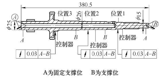
Figure 5 Input shaft part drawing Inner input shaft machining process
Internal input shaft alignment process
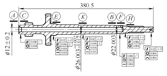
Figure 6 Straightening process requirements Conclusion
The DCT (Dual Clutch Transmission) is also known as the DSG (Direct Shift Gearbox) direct shift transmission. The dual clutch transmission technology has been used in racing cars for nearly 70 years, and it has only been used in production cars for a few years. The dual clutch transmission technology has obvious advantages, combining and surpassing the flexibility and speed of the manual transmission, the comfort of the automatic transmission, and saving fuel and energy. In recent years, the rapid development of China's automobiles and the huge market have promoted the commercialization and popularization of dual-clutch transmissions.
As shown in Figure 1, from the outside, the DCT is composed of two outer casings (separate from the shell and the shell) and is completely enclosed. The lightweight design of the clutch shell and the transmission case are made of aluminum alloy. The assembly surface assembly holes are machined by a precision CNC machining center and assembled into a complete transmission. The overall shape is not much different from the traditional manual transmission and automatic transmission.
The sectioning (see Figure 2) shows the structural difference between the DCT and the conventional manual transmission and automatic transmission. That is, the DCT has two input shafts, one is an inner input shaft, and the other is an outer input shaft. The two hollow shafts are sleeved together to transmit engine power, and two output shafts correspond to the clutches 1 and 2, respectively.
In the inner input shaft assembly shown in Fig. 3, the assembly positional relationship of the dual clutch internal gear transmission system can be clearly displayed. The inner input shaft and the outer input shaft are both hollow shafts, and the inner input shaft sleeves are in the outer input shafts, and each is responsible for gear transmission of different gear positions. There are one, three and five gear meshing gears on the inner input shaft, and two, four and six gear meshing gears on the outer input shaft. When the meshing gears of different gears mesh with the gears of the corresponding gears, the gear transmission system is in operation.
The gears of different gears are shifted by the shift fork. Different gears are hung and the gears are shifted by gear transmission. One of the main features of the dual clutch transmission differs from that of the conventional transmission in that one gear is in operation and the other shift position is in a ready state, thereby achieving seamless connection of shifts and smooth shifting.
The internal projection and physical perspective of the DCT are shown in Figure 4, clearly showing the positional relationship of each transmission part. The dual clutch output shaft 2 is also connected to the differential. When the vehicle is turning, the inner wheel slides due to the outer wheel sliding, and the differential adjusts the two side shafts to rotate at different speeds, so that the two wheels are as pure rolling as possible. Will slide to do not equidistant driving, reducing the friction between the tire and the ground.
The DCT has two input shafts and two output shafts, all of which are hollow shafts. The output shaft is relatively short and relatively difficult to machine. The inner input shaft is long and thin. The total length of the shaft is 380.5mm, the outer diameter is 25mm, 26mm, 22mm, the inner hole is 12mm, and the hole depth is 293.3mm (see Figure 5, A is the fixed support position, B is the mobile support position). The accuracy of the shaft is required to be high, and the required straightening runout after heat is not more than 0.03 mm. Drilling deep holes and straightening are difficult machining points for metal cutting and heat treatment, respectively. We use German TBT deep hole drilling technology and German MAE automatic straightening technology.
The inner input shaft is the same as all the shaft processing routes, and is also subjected to blanking, forging blank, normalizing, roughing, finishing, hot front gear processing, heat treatment, thermal post-processing and final cleaning oil seal storage. The company's rough forging, normalizing and roughing are all outsourced. The internal machining process starts from the finishing car. According to the internal input shaft part structure, the specific process is: one end of the finishing car → the other end of the finishing car → hobbing (one gear meshing tooth) )→Rolling teeth (three-and five-speed meshing teeth)→Squeezing edge (one gear meshing tooth)→Squeezing edge (three-and five-speed meshing teeth)→rolling spline→drilling deep hole→drilling hole→preheating cleaning→ Heat treatment (carburizing quenching + heat cleaning + tempering) → cleaning shot blasting → strengthening shot blasting → straightening → hard tank → grinding outer circle → cleaning → sealing oil into the warehouse.
The inner input shaft is made of low-carbon alloy steel (20MnCrS5). The surface is made of high hardness and high strength by carburizing and quenching, and the core is strengthened. In order to avoid cracks in the parts when straightening after heat treatment, two different process arrangements are tested:
Solution 1: Carburizing and quenching → cleaning after heat → cleaning shot blasting → strengthening shot blasting → straightening → tempering.
Option 2: carburizing and quenching → cleaning after heat → tempering → cleaning shot blasting → strengthening shot blasting → straightening.
According to the structural characteristics of the parts, four support points were selected, three straight control positions, and the straightening process requirements are shown in Figure 6. The test shows that the parts are prone to cracks when the plan is straightened, and the proportion of cracks generated by the parts when the plan is straightened is greatly reduced. The straightening process uses a MAE automatic straightening machine, equipped with an automatic crack detection device and a screening mechanism.
The DCT dual clutch transmission reduces manufacturing costs and improves the maturity of the technology. In particular, the maturity of processing and manufacturing technology will determine its future destiny. Only by solving the processing difficulties and improving the level of process technology, DCT will have better performance in the market. The slender hollow shaft alignment problem has zero cracks or allows critical cracks as an industry problem, and everyone needs to work together.