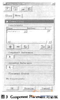
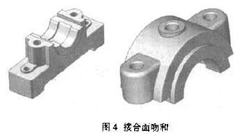
(4) Joint surface positioning. Select the Mate item under the Conetraint Type column in the Component Placement dialog box shown in Figure 3. Select the joint plane of the bearing cap and the bearing housing, as shown in Figure 4.
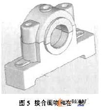
(5) Cylindrical surface positioning. Select the Insert item in the Canstrairtt Type column of the component Placement dialog. Select the cylindrical surface of the bearing corresponding to the bearing seat and bearing cap, as shown in Figure 5.
(6) Axis positioning. Select the Align item under the Constraint Type column in the Component P2aesment dialog. Select the axis of the threaded hole on the bearing housing and the axis of the corresponding threaded hole of the bearing cover, and click the OK button in the Component Placement dialog box to complete this step.
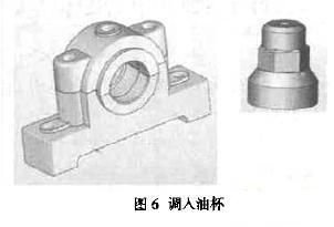
(7) Adjust the oil cup parts. Execute the component Assemble command in the menu manager, select the capped oil cup in the Open dialog box, and click the Open command to adjust the assembly window. As shown in Figure 6.
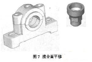
(8) Joint surface translation positioning. Select the Mate item under the Gostraint Type column in the Gomponent Placement dialog. Select the bearing cap to place the top surface of the oil cup and the bottom surface of the oil cup, and click the offset property of Mate in the Component Placement dialog box to modify the value to -5. As shown in Figure 7.
Previous page next page
Feeding Peristaltic Pump,Liquid Transfer Pump,Peristaltic Pump,Viscous Liquid Pump
Baoding Chuangrui Precision Pump Co., Ltd. , https://www.chuangruipump.com